


Survey of rebars, methods of cutting, bending, binding and placing in position
Round hot-rolled mild steel bars is the predominant method of concrete reinforcement. Rebar works involve straightening and removal of kinks, cutting to length, bending to the required shape, laying in position, laying cover blocks from shutters and tying or binding to adjacent rebars. Factory-made rebar does not require cutting and bending at the site. Similarly, pre-welded wire fabric does not require binding at site.
- Rebar: CTD, TMT, FBE, CRS; Billet / Iron-Ore
- Circular bench/hand-held saw
- Bar Bending Schedule; Bench and Machine
- Binding wires; Mechanical Couplers
- Cover Blocks; Chairs
Reinforcement Steel Bars or Rebar
Common bar diameters in use are 6, 8, 10, 12, 16, 20, 25 and 32mm. Bars are supplied in length of about 40 feet (12m), folded when transported in trucks or straight when transported in long trailers. In shop working, bars of diameter less than 12mm may also be supplied in coils.
“Mining companies manufacture steel from iron-ore whereas other companies manufacture steel by re-rolling billets & scrap”
Rebars are classified on various bases:
- Based on Grade of Steel: Common grades of steel are 415MPa and 500MPa. Bars of these grades are formed by elongation without heating and twisting to form surface ribs; hence these are called Cold Twisted Deformed (CTD) bars. As against this, steel bars of mild steel grade 250MPa, the Plain round bar is now seldom used in industry.
- Based on Process of Manufacture: Invariably, rebar is manufactured by hot rolling, followed by cold treatment to improve strength. However, high-grade steels are more brittle. More recent manufacturing uses processes such as annealing (slow cooling) or quenching (rapid cooling) that attempts to improve the ductility of high strength rebars. A common method is a quenching process in cold water, otherwise called Thermo-Mechanical Treatment (TMT)
- Based on Metallurgy: There are at least two common manufacturing processes today. Mining companies manufacture steel from iron-ore by the Basic Oxygen Process (Linz-Donawitz or Bessemer converter). Other companies use Electric Arc Furnace for melting and re-rolling of steel billets or direct-reduced iron (also called sponge iron), with varying quantities of steel scrap. Steel billets or sponge iron are supplied to re-rolling mills by mining companies whereas scrap is collected from discards. Direct rolled steel is expensive as the manufacture of steel from iron-ore requires closer process and quality control.
- Based on methods of corrosion protection: High-grade steels are also more vulnerable to rusting than plain mild steel bars. Various methods are used to enhance the useful life of steel. Anticorrosive coatings at site and fusion-bonded epoxy FBE coating at factories are common application methods. Coated steel is alleged to have reduced bonding with concrete. Doped or alloy steels, with varying chromium content such as stainless steel (Grades about 310MPa), are also used for corrosion resistance. Some companies claim to manufacture corrosion-resistant steel CRS by reducing phosphorus content and providing integral oxide films. Galvanized rebars are also used in extremely severe exposure conditions.
The diameter, grade, ductility and corrosion resistance characteristics of steel are laid down on drawings vide architectural or structural specifications. Metallurgical manufacturing procedure (Iron ore based or re-rolling based) is also usually characteristically specified by the client in tender specifications. Therefore, construction engineers’ choice on the type and size of steel is limited.
Rebar Cutting
Most common method for rebar cutting is Bench Cutting using a circular bench saw and carbide disc blade. Bench cutters could be Corded (Typically 15A/120V, 7.25″ Carbide Blade Diameter) or Battery Powered (Typically 18V, 6.5″ Carbide Blade Diameter). The blades are characterized by diameter and number of teeth. The cutter may be attached with accessories such as dust blowing system, dust collection system and electric motor brake arrangement for better performance. The effort of rebar cutting machine and consumption of blade depends on the area of cutting, although bar bending works are usually measured in tonnage. Typically, a blade can make about 100 cuts on 16mm bars.
Hand-held circular saw and hand-held reciprocating saws are also used occasionally for rebar cutting. In manpower-intensive works, rebar cutting is done by hammer-chisel striking or using axe-saw blades.
One (or no) cut is necessary for each designation of the bar bending schedule. Combination of different saw capacity with different blade diameter/teething produces different efficiency in cutting. Since mobilization of cutting machines is not very costly, requisite cutting machines are always made available on plant in construction sites, even if they are used sparingly. Hence, blade consumption is more significant than saw performance. Thus, for all practical purposes, it may be assumed that saw and blade performance are mutually independent.
Rebar Bending
The desired final shapes of bars is described on the Bar Bending Schedule BBS. The BBS is produced by the contractor engaged in bar bending. Contrary to some popular belief, it is impossible to do bar bending without a BBS, and on all projects, at least an informal BBS is made by the rebar fitter, even if a formal BBS has not been issued by the engineers. Many engineering firms resort to scheduling of bar bending at the site, due to the convenience of full-scale layout and hence more controlled assessment at site. As scheduling BBS on full-scale layout requires a predominant portion of shuttering to be completed, this may considerably impair the speed of construction.
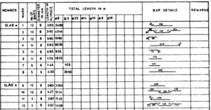
“Every bar bending job has a bar bending schedule – at least an informal one made by the rebar fitter on full-scale layout”
Rebar Bending is achieved either manually by bench bar bending using a bending lever or using a bar bending machine. In both methods, the bending lever or loading roller applies a bending moment that exceeds plastic sectional moment capacity on the rebar, about two or more fulcrum. A simplified bar bending machine shown below provides a schematic mechanism of operation. Theoretically, after the fibre stress approaches yield strength of steel at the bending point, the desired angle of bend can be achieved without additional force due to the yielding of steel. However, it is necessary to apply an additional but lesser effort by pushing or pulling the rod, to overcome (1) yielding of adjacent sections to the plastic hinge and (2) strain hardening of steel beyond some yield plateau.
 |
 |
;
Bending is also limited by the chord distance of the arc: the distance required for the movement of the lever or roller from the nearest fulcrum point, to achieve the desired angle of bend. This requirement decides the distance between fulcrum and loading in machine bending and the width of lever in bench bending. Hence, bar bending benches and levers depends on bar diameter, such as 8-10mm bench, 8-12mm lever, 12-25mm bench, 16-25mm lever. Using a minimum bending radius of 4d for cold twisted rods, as specified in most design Codes, a 90-degree L-bend requires a chord length of 5.65d and 180-degree U-hook of 8d – inside to inside. As the entire chord length transforms into a circular arc during bending, the plastic hinge becomes as long as this chord length. High-grade steel being less ductile, CTD rods of larger diameter (16mm and above) are likely to break before the entire length of hinge is plasticized for large angle of bend such as 180 degrees.
Using the minimum bending radius vide corresponding lever settings and ignoring the slightly additional effort beyond initial yielding, effort for bar bending is by far independent of the angle of bend. However, bending effort is significantly influenced by the number of bends in the bar shape and the bar diameter.
Rebar Binding
Depending on the ease of handling rebar cages or mats are tied either before or after laying in position. Binding is typically carried out by tying binding wires or using spot welding. Binding wire is supplied in long coiled strands of typically 18 Guage (1.02mm) or 20 Guage wire. Material may be galvanized steel or black annealed steel. The wire may be tied using a wire tying tool or electric rebar tyer. Binding wire may be tied either directly or after folding once. The tie may be applied in different methods as shown in the following figure from Reinforcing Steel Institute:
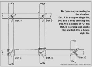
Double fold single tie binding is typically used for beams and columns with bar diameter including and above 16mm, whereas single fold single tie is used for lightly loaded applications. For double folds and bar diameter equal or above 16mm, the coil bundle is cut into 2-3 arcs, whereas for double/single fold for bar diameter equal or below 12mm, the bundle is cut into 4-5 segments. Main bars of columns and beams are tied typically at 2-5 locations at laps. Stirrups (or links) are ties to main bars at 4-6 locations. Sidebars of beams, slab bars and footing mats are tied at every second or third intersection.
“It is not necessary to tie rebar at every intersection”
In cases of space constraints, straight rebar laps are replaced by mechanical coupling. Mechanical coupling uses the following methods:
- Threaded sleeve rebar coupler, where both rebar and coupler are threaded
- Crimped sleeve coupler, where the sleeve is crimped using a hydraulic crimping tool after coupling to fit the ribbed surface of rebar
- Injected sleeve coupler, where space between coupler and rebar is filled with molten metal
- Collared rebar that is bolted together
Cover Blocks & Chairs
Cover blocks are available in cement mortar and PVC, in sizes accommodating 20mm, 25mm, 40mm, 50mm and 75mm, depending on the requisite cover to steel. The blocks are inserted into position, during or after the erection of rebar cage or mat.
Cover blocks for slabs, floor mats, footing mats etc are laid at intervals of about 750mm on length of rebar or say about 2 blocks per sqm. For beams, 3-4 cover blocks are placed at about 750mm length of beam – one or two to regularize the bottom cover, and two blocks to fix side cover. For columns, usually 4 cover blocks are used, one on each corner at column shutter top, for each lift.
Commonly rebar is bent in the form of a chair to hold top layer of steel in slabs and footings. The number and size of chairs are governed by design, through normally about 2 chairs are used per sqm. Various PVC and steel Rebar Hi-Chair is also now commonly available.
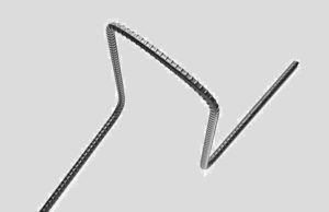
A Typical Site-bent Rebar Chair
“The content presented above is the sole property of Adept Algorithms and shall not be reproduced in part or whole without prior permission”